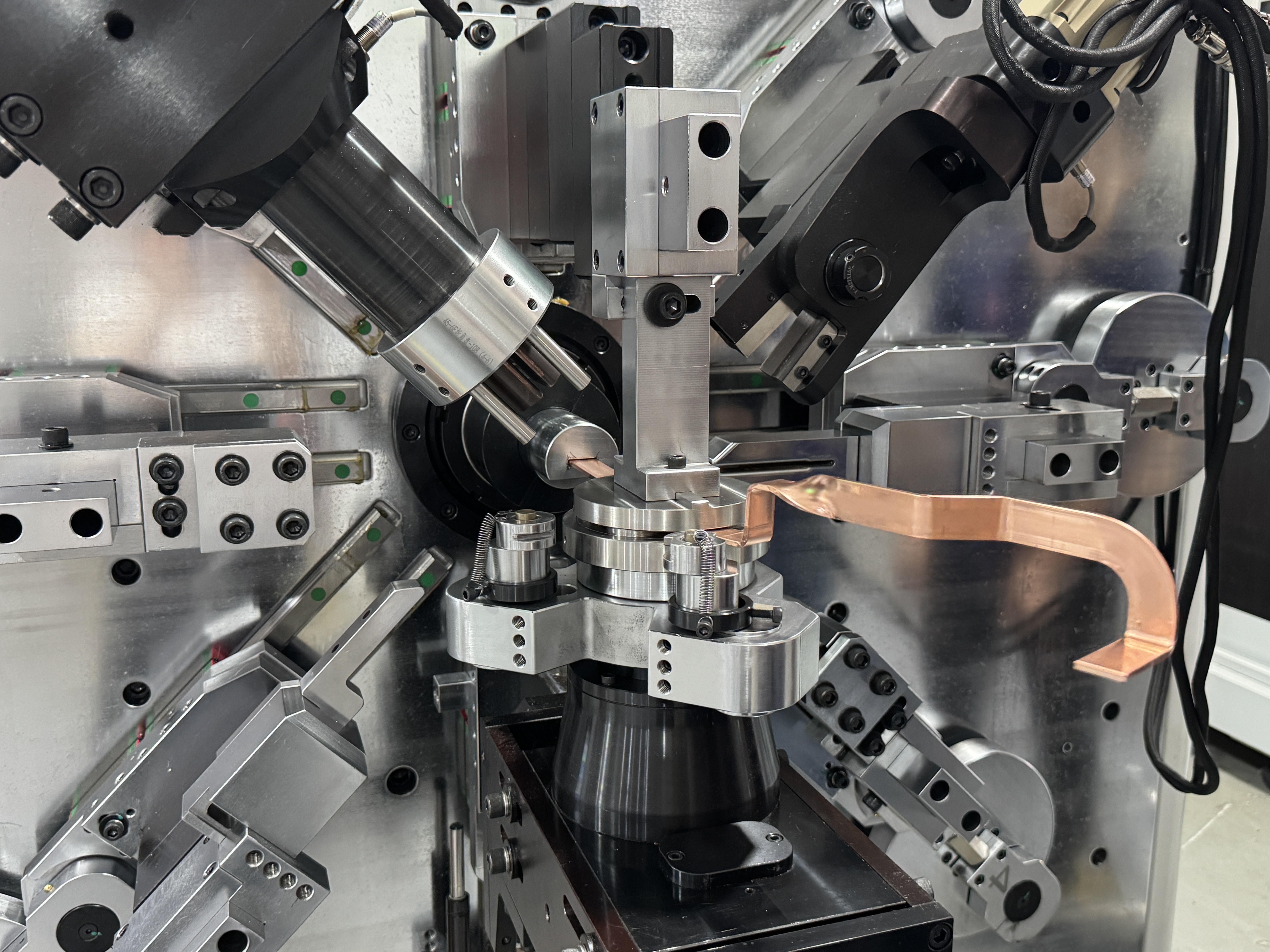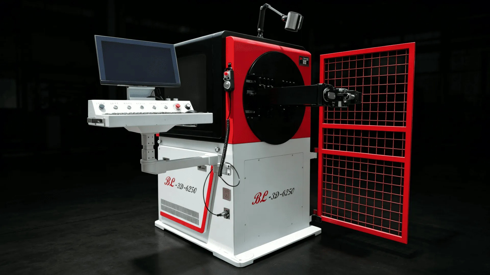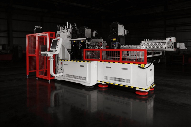


A cracked busbar usually gets blamed on the machine that bent it. When I cut a cracked part open and look at the fracture face, though, nine times out of ten the crack was decided before the bar ever reached the bending head — in the material temper, the rolling direction, or the burr left by the cutting step upstream. A properly built busbar bending machine repeats a 90° angle within ±0.2°, so when cracks show up across a batch, the angle control is almost never the cause. Here is how I separate material problems from setting problems on the shop floor.
Four Upstream Causes I Check First
The Radius Is Too Tight for the Temper
Copper busbar looks soft, but most of it arrives half-hard, and every temper has a minimum radius it will survive. A copper busbar bend radius that works for annealed bar can tear half-hard bar of the same size. My habit is to start with an inner radius equal to the material thickness and step it up until the crack disappears, instead of suspecting the machine first. Coated bar gets stricter rules on our floor: on flat bends the inner radius stays at one times the bar width (bulge allowance 1.6mm per side), and on vertical bends one times the thickness (1.5mm per side). Bare copper tolerates tighter radii, but grain and edge discipline still apply.
The Bend Line Runs with the Grain
When the bend line runs parallel to the rolling direction, the grain boundaries land right on the tension side of the bend, and the crack comes out long and straight. Bend across the grain and the fracture face turns dull and fibrous — a much safer failure mode. If cracks come and go within one batch, the leveling line or the way operators load bars into the magazine is usually the reason. Cut-to-length bar should be stacked in one orientation and marked.
The Cut Edge Carries the Crack In
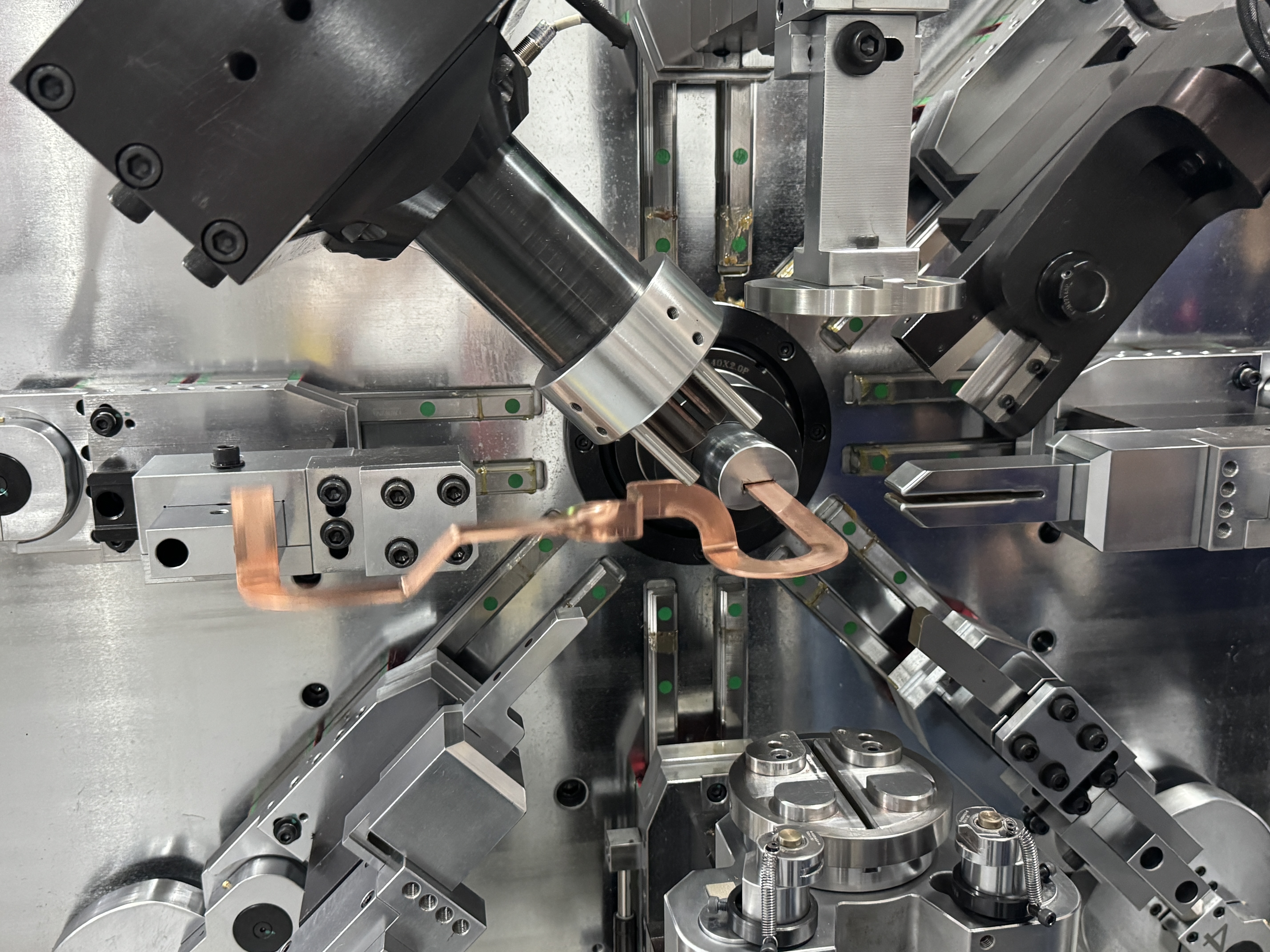
The outside of the bend is in tension. A burr or micro-crack from shearing or sawing sits exactly on that surface, and the fracture starts at the burr tip. If the crack consistently begins on one edge of the bend line, suspect the cut edge first. Deburr before bending; laser-cut edges behave noticeably better than sheared ones.
Mixed Tempers Inside One Batch
Suppliers change melt lots and annealing schedules drift. The same drawing can crack on some bars and pass on others from the same delivery. No machine adjustment fixes that — ask the supplier for a temper certificate and quarantine the suspect lot.
A 20-Minute Triage Sequence
Run these in order, changing one variable at a time. First, read the fracture face: bright, coarse grains point to a tight radius; dull, fibrous texture points to grain direction or temper. Second, bend a confirmed-annealed offcut. Third, rotate the bar 90° and bend again. Fourth, slow the bending speed down. Fifth, increase the radius one step. Whichever step makes the crack disappear points at the root cause.
What the Machine Can Fix, and What It Cannot
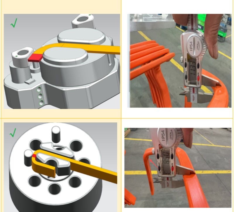
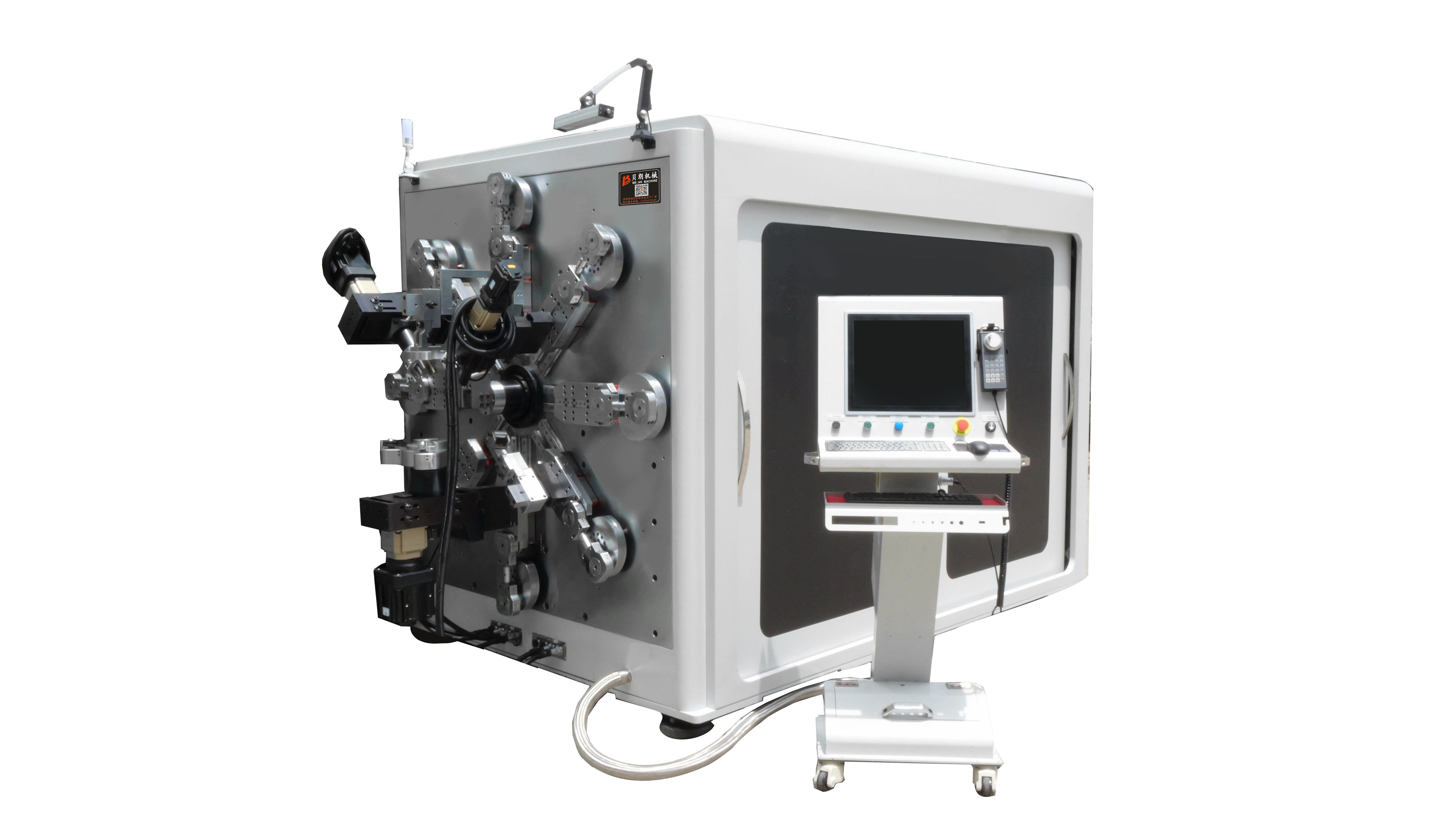
Inside a sound process window, the machine earns its keep. The eight bending arms on our 16-axis segmented busbar bending machine (TP-DL-45-6E, 12–45mm wide × 2–6mm thick) work in sequence, ease off bend speed before a tight radius, hold ±0.1° on flat bends and ±0.2° on vertical bends, and reproduce a proven parameter set the same way ten thousand times. Thicker sections — 15–60mm wide × 2–8mm thick — go to the 6000KG frame of the TP-DL-60-8E busbar bending machine, where the stiffer support matters most on heavy bar. What no machine can fix: the wrong temper, a random rolling direction, or a burr left on the edge. Those belong to the material side.
Quick Diagnosis Table
Before touching any setting on the busbar bending machine, match what you see against this table:
| Symptom on the part | Most likely cause | First move |
| Crack starts at the outer bend edge, bright and coarse-grained | Radius too tight for the temper | Step the radius up |
| Crack runs along the bend line, starting at one edge | Burr or micro-crack on the cut edge | Deburr before bending |
| Some bars crack, some do not, same batch | Grain direction or mixed temper | Standardize bar orientation; request temper certificate |
| Orange-peel surface, then fracture | Radius small relative to thickness, over-working | Increase radius, slow the bend |
| Same position cracks on every bar | Tooling or clamp face damage | Inspect die and clamp faces |
Radius Rules Are Kept, Not Tuned

The economical logic on our floor is simple: fix the radius rules, the deburring step and the bar orientation into the process sheet, then let the busbar bending machine handle repeatability — feeding accuracy of ±0.1mm over 300mm and ±0.2° per angle means one validated setup stays valid across the whole run. Every busbar bend cracking complaint I have traced came back to the material side or the process sheet, never to a servo drifting out of spec. Feed accuracy, angle accuracy and a 100,000-cycle endurance run before shipment are there to keep it that way.
If a crack has you stuck, send us the drawing plus a photo of the fracture face, with the width, thickness, temper and radius called out, and we will tell you straight whether to change the settings or the material. The right busbar bending machine setup only pays off once the bar coming into it is consistent. BELAN Machinery, your expert provider of automotive wire forming solutions.