
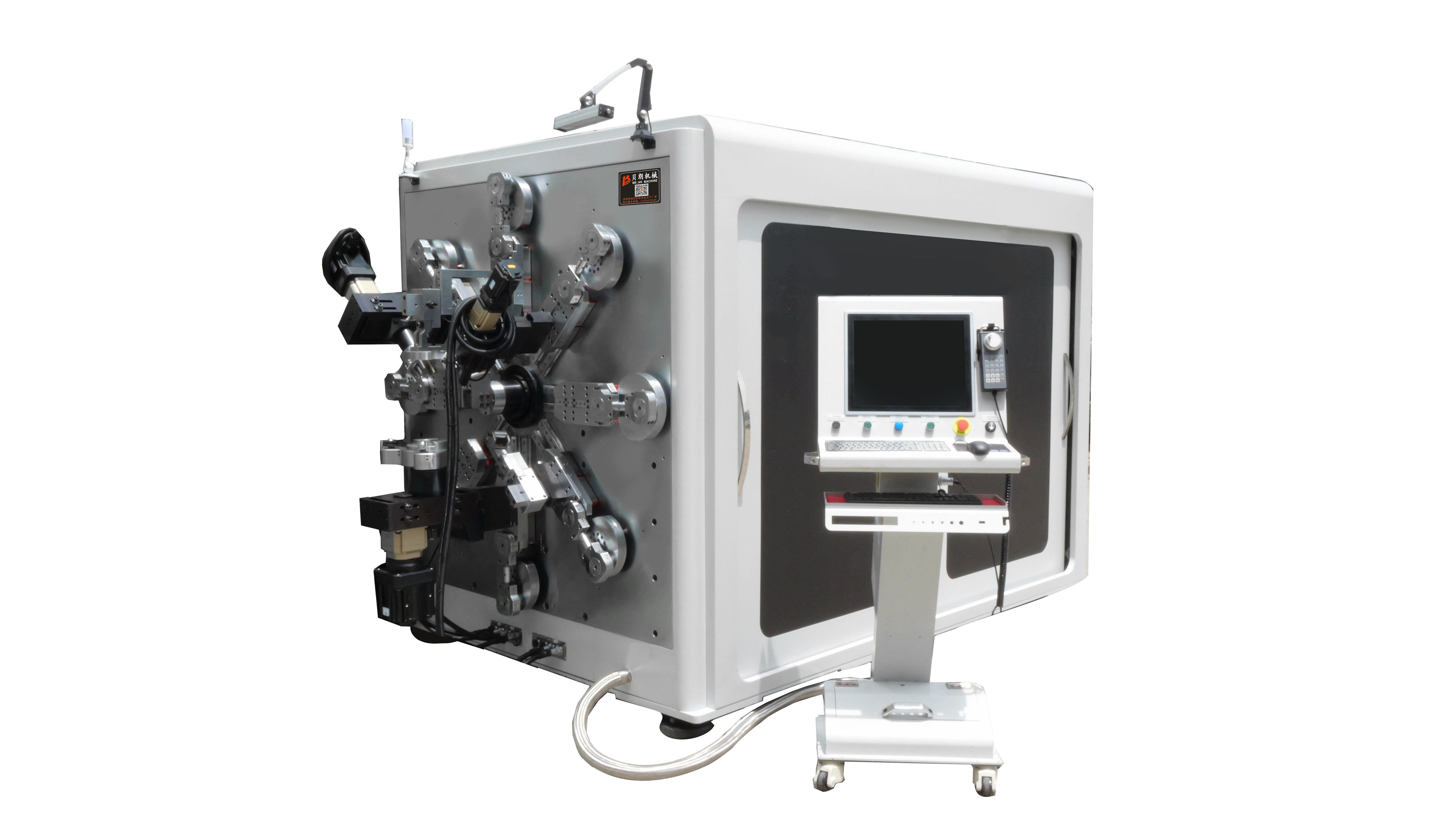
Last autumn a connector supplier sent a drawing package and asked whether one busbar bending machine could run their bar family. I sent back a layout for nineteen machines. They thought I had opened the wrong attachment. That cell now releases one finished bar every 75 to 85 seconds, and the bender they first asked about is one station inside it.
Start With Weekly Bar Count, Not With the Machine
Most shops work this decision backwards, then discover the cost sits upstream and downstream of the machine.
Follow one bar: it leaves the straightener, gets carried to a saw, a press, then a bender. Every carry adds a handling mark to a coated surface, a layer of tolerance stack-up and a labour hour nobody quotes. The further the bar travels, the more expensive a defect becomes.
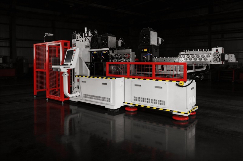
The cell we built runs 30 m by 12.25 m — 367.5 m² — with nineteen machines linked by six-axis robots. No human hand touches the part between stations.
What the Nineteen Stations Do
| Station group | Equipment | What it delivers |
| 1 | Coil feed, straighten, cut, laser mark | 800–3000 mm cut length with a traceability code |
| 2 | Six-axis robot transfer | Bar never touches a bench |
| 3 | Double-end peeling | 10–100 mm bare copper at each end |
| 4 | Double-end punching, 60 t | Both ends formed in one stroke |
| 5 | Brush deburring | Four faces deburred |
| 6 | Plasma / dry-ice cleaning | Bare metal at the weld joint |
| 7 | Terminal welding, both ends | Two terminals, one pass |
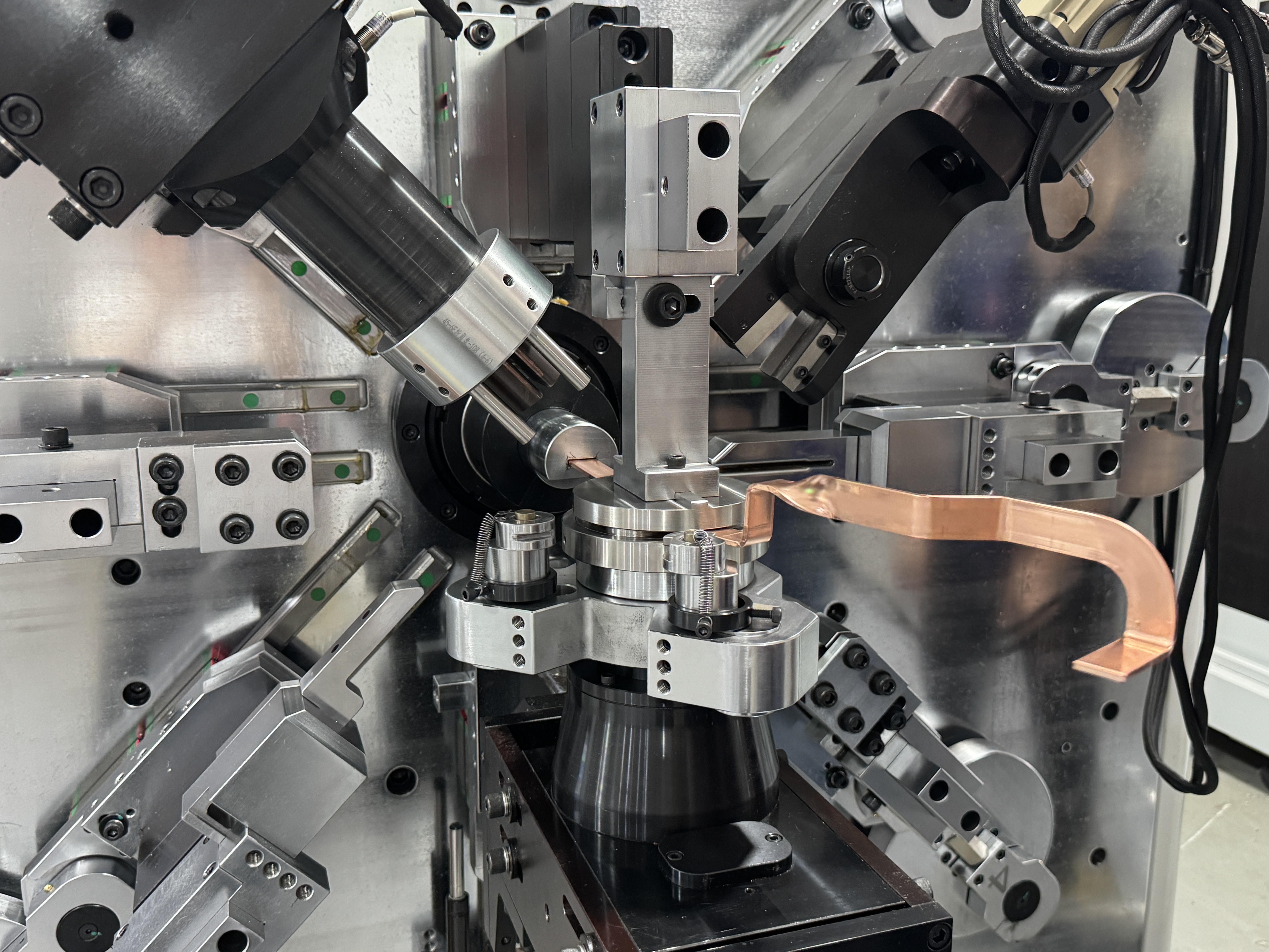
| 8 | Bending, 13 axes | Flat, edgewise and twist bends |
| 9 | Corrective bending | Angle trim before release |
| 10 | Robot unload | Finished bars to racks |
Working range of the cell: 50–240 mm² section, 15–40 mm wide, 2–6 mm thick.
Bend After Weld, and Why That Order Is Fixed
What arrives at the bend head is no longer flat stock
This is where most line designs fall apart. The bar reaching station eight already carries terminals welded on both ends, a plasma-cleaned surface and a laser code. The clamping face is no longer clean rectangular stock — it is a weld bead, a terminal root, a peel transition.
A point-contact grip slips on that geometry, and it crushes the weld. Tracked-belt feeding earns its place here beyond coating protection: it spreads clamping force across the whole bar face and steps around the weld and terminal.
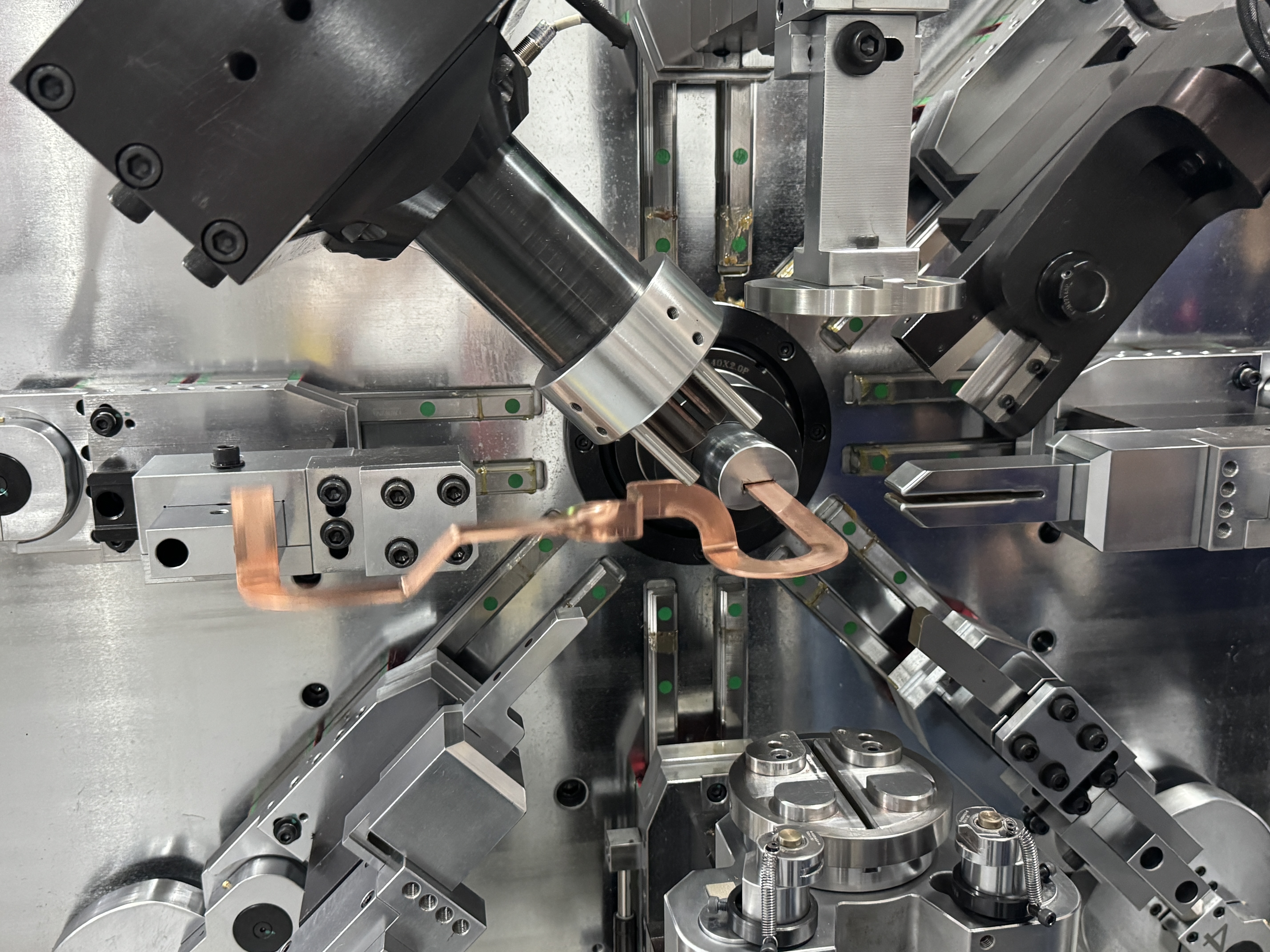 The busbar bending machine at station eight cannot run a welded bar on a pinch grip.
Corrective bending is a station, not a rework bench
On a 2.4 m bar, angle drift accumulated over seven upstream stations shows up at the bend. A dedicated trim station clears it in about two seconds: measure, nudge, release. Without that station, an out-of-angle bar leaves the line, joins a pallet and waits for a fitter. Continuous flow stops there.
Where 75 to 85 Seconds Comes From
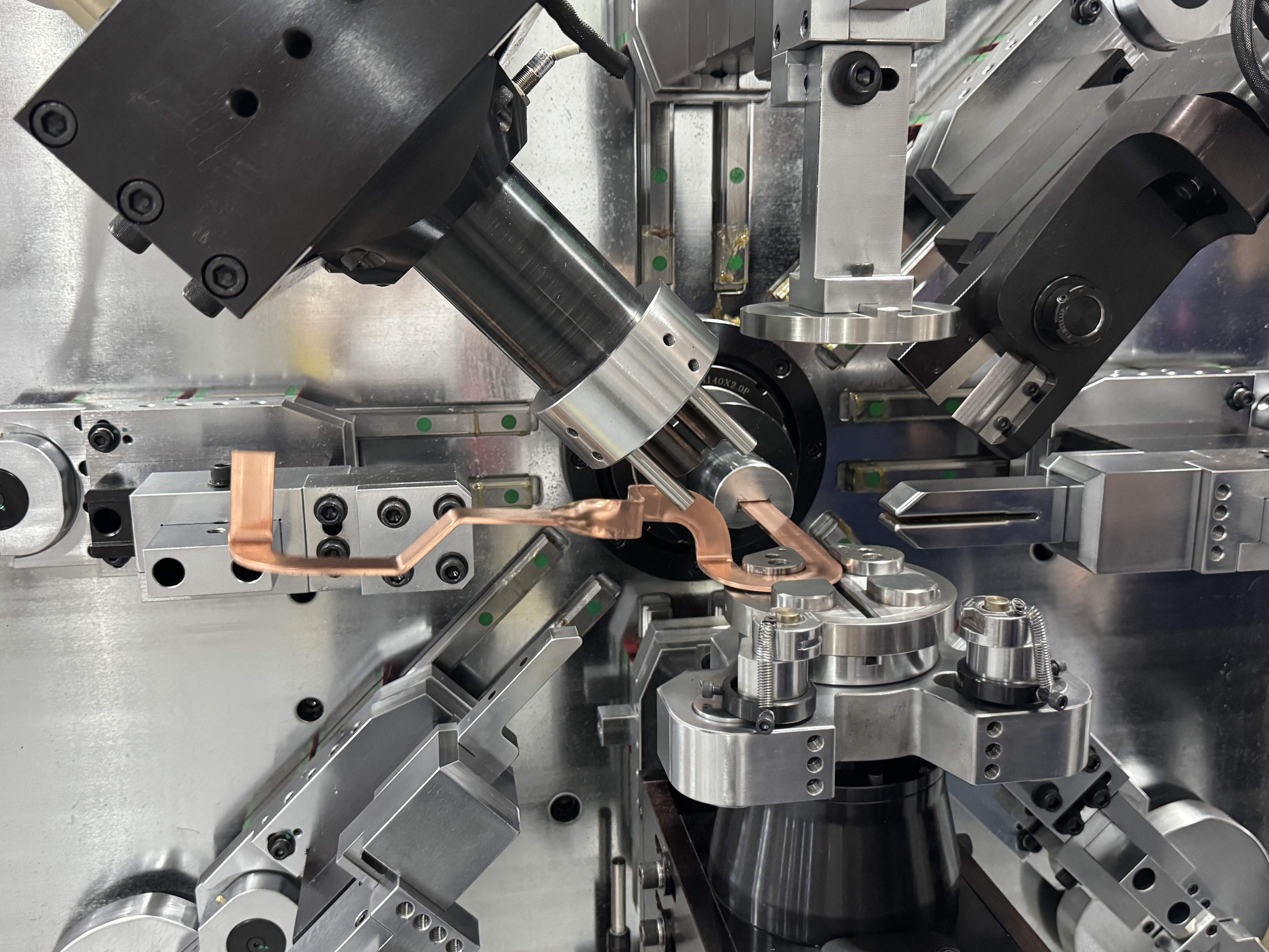
Look at the stations individually: straightening 30 s, punching 40 s, welding 50 s, bending 75 s. Run those four in sequence and you are already at 195 s. The cell hits 75–85 s because the cycles overlap — station nine is preparing while station eight is still forming.
The price of overlap: the slowest station sets the beat. On this line the slowest station is the bend. That makes the bender a capacity decision, not a convenience purchase. A bender slower than the welder wastes the welder; a bender far faster than the rest wastes capital.
The accuracy floor has to hold up too: ±0.2° repeatability on 90° bends, ±0.1 mm feed error at 300 mm, and a 100,000-cycle loaded run-in before any machine ships. On a cell producing hundreds of bars a day, an unstable single machine undoes the cleaning and welding done in the six stations ahead of it.
When One Machine Beats Nineteen
An integrated line is not a universal answer. It works when one or two bar families run at high volume, week after week. Widen the product mix or shrink the lot size and the changeover overhead across nineteen stations eats the throughput gain.
| Decision point | Line fits | Standalone machine fits |
| Weekly volume | Thousands of bars, one family | Tens to hundreds, volatile |
| Product mix | One or two families, narrow sections | Many families, order-driven |
| Coating types | One or two (PA12, mica) | Frequent switching |
| Welding | In-house terminal welding, high volume | Outsourced or manual |
| Floor space | 350 m² continuous | Tight, phased investment |
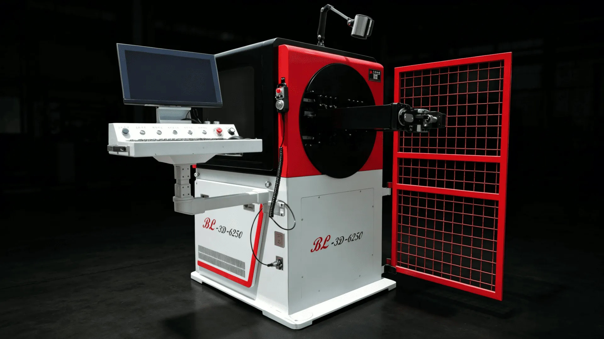
The standalone route looks like this: one 16-axis busbar bending machine such as the TP-DL-45-6E, 12.0–45.0 mm wide by 2.0–6.0 mm thick, tracked feeding and a straightening unit, one operator running two machines. Where copper and aluminum mix and coatings change often, the 13-axis busbar bending machine BL-TP-50-7E covers 15–45 mm copper at 1.0–7.0 mm and 15–50 mm aluminum at 1.0–8.0 mm, with pressure adjustment instead of wheel changes.
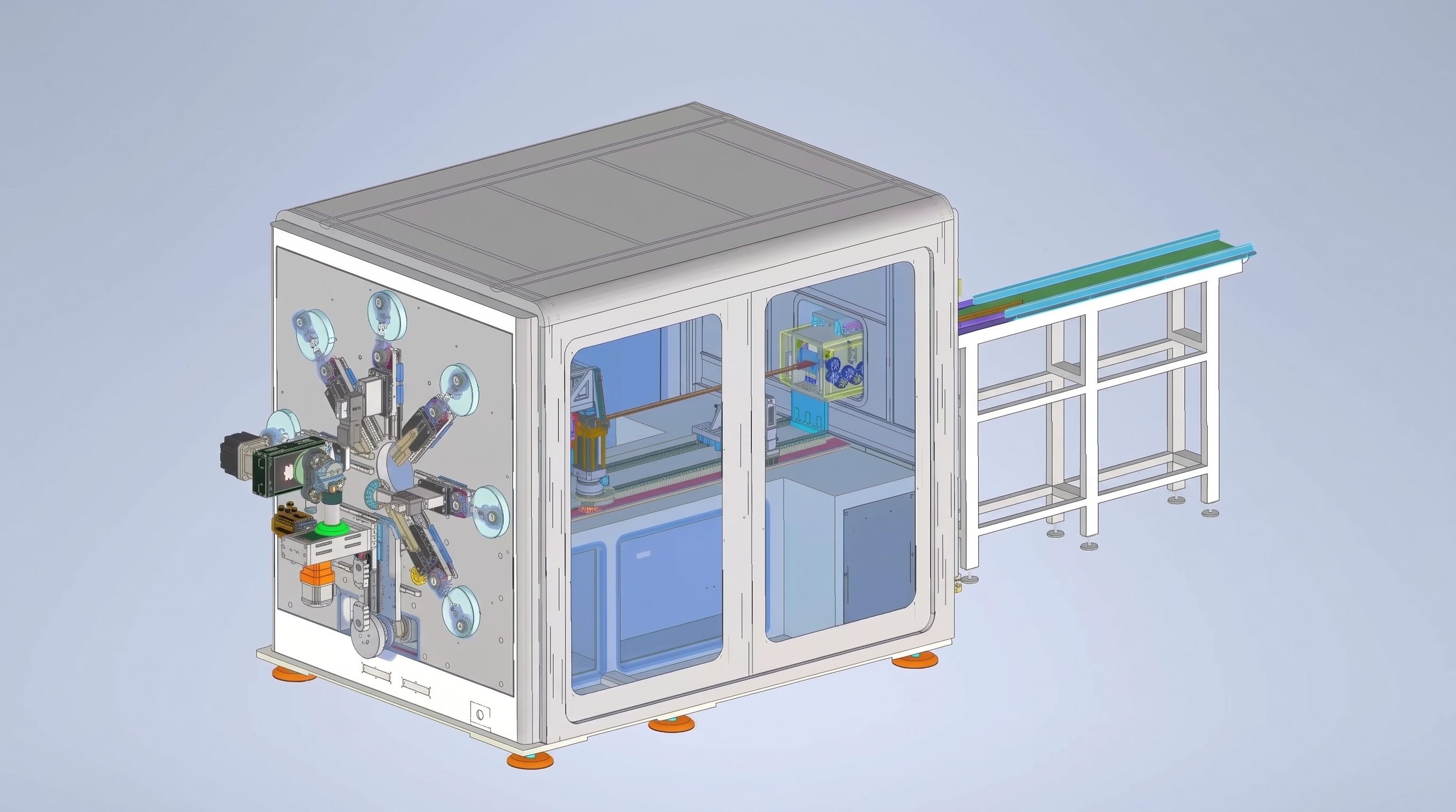
Phasing works better: start with straightening, cutting and bending, then add peeling, punching and welding once volume justifies them. Cheaper than a full cell running at half load.
What I Need Before I Draw a Layout
- Bar drawings: section, width, thickness, developed length, bend count
- Weekly volume and shift pattern per bar family
- Coating: bare copper, PA12, PVC-mica, aluminum
- Terminal spec and weld process: ultrasonic, laser, TIG
- Available floor, length by width, column spacing, crane height
- Target cycle time, and whether the output feeds pack assembly or switchgear
- Existing equipment that has to be absorbed into the cell
With those seven items I can return a station-by-station cycle table and a floor plan, not a yes-we-can email.
If your volume has not reached the line threshold, do not force it. Send the drawings and weekly count first — we will check whether a single busbar bending machine holds the load. If it does, buy one machine. If it does not, we talk about the busbar production line and build the NEV busbar manufacturing cell around your bar families, not around a catalogue. BELAN Machinery, your expert provider of automotive wire forming solutions.