

Introduction
A quotation request for a wire forming machine often starts with the same sentence: "We need to make this part." The drawing may show a simple bracket with three bends in one plane, or a seat frame component with a dozen bends twisting through two planes. Both buyers use the same words, yet the machines, tooling, and process behind each part differ fundamentally.
Choosing a wire forming machine for complex 2D and 3D wire components is therefore not a matter of comparing spec sheets. It starts with understanding what the part geometry actually demands: how many planes the bends cross, how the wire must be supported and rotated, where tolerances are tight, and how the production volume will stress the tooling. This guide works through that evaluation in the order a manufacturing engineer would apply it — from part geometry to machine architecture, tooling, and the point at which custom equipment becomes the right answer.
What Separates a 2D Part from a 3D Part?
A 2D wire component is formed entirely in a single plane: every bend shares one bending axis, the wire is never rotated between features, and the finished part lies flat. Brackets, hooks, clips, grilles, and simple frame members are typical. The challenge in 2D work is usually not geometric ambition but precision and speed — repeatable angles, consistent radii, and short cycle times.
A 3D wire component requires bends in multiple planes, which means the wire must be rotated — or the forming head must travel around it — between features. Seat frames, seat cushion assemblies, wiper linkages, and most automotive structural wire parts fall into this category. The machine must control not only where each bend happens but the wire orientation throughout the sequence.
The distinction sounds simple, but it determines almost everything downstream: whether the machine needs a rotary head or rotary die, how many axes are genuinely used, how the wire is fed and gripped, and how much engineering sits behind the tool set. Parts that look similar on paper can sit on opposite sides of this line, so the first step in selection is classifying the real geometry — not the nominal product name.
Why the 2D/3D Distinction Drives Machine Architecture
For genuinely flat parts, a dedicated 2D wire bending machine is often the most efficient choice. With fewer axes to coordinate, setup is simpler, programming is faster, and the machine can dedicate its rigidity and speed to high-volume flat forming. Buying multi-axis capability for parts that never leave a single plane typically means paying for rotation the process will never perform.
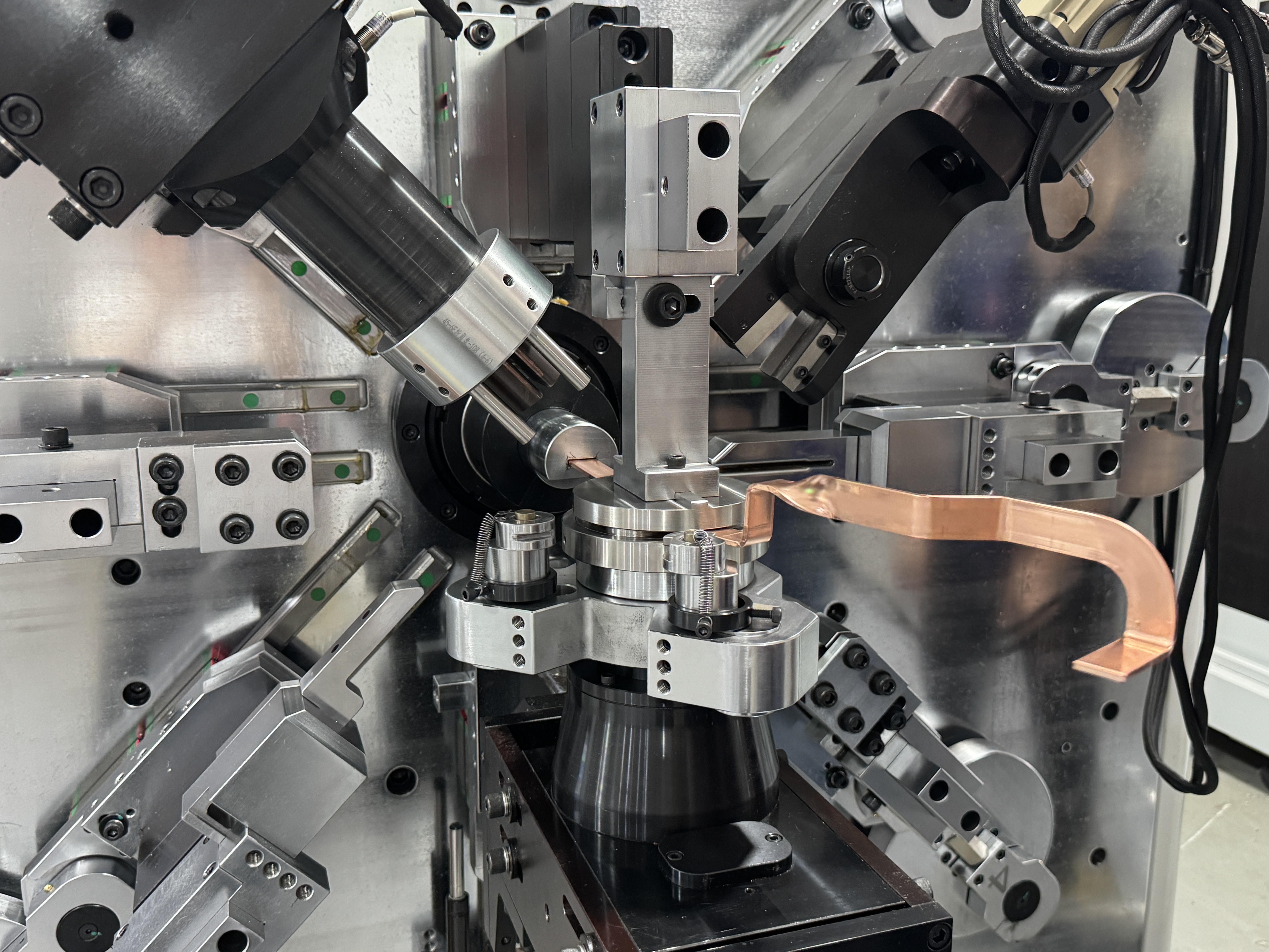
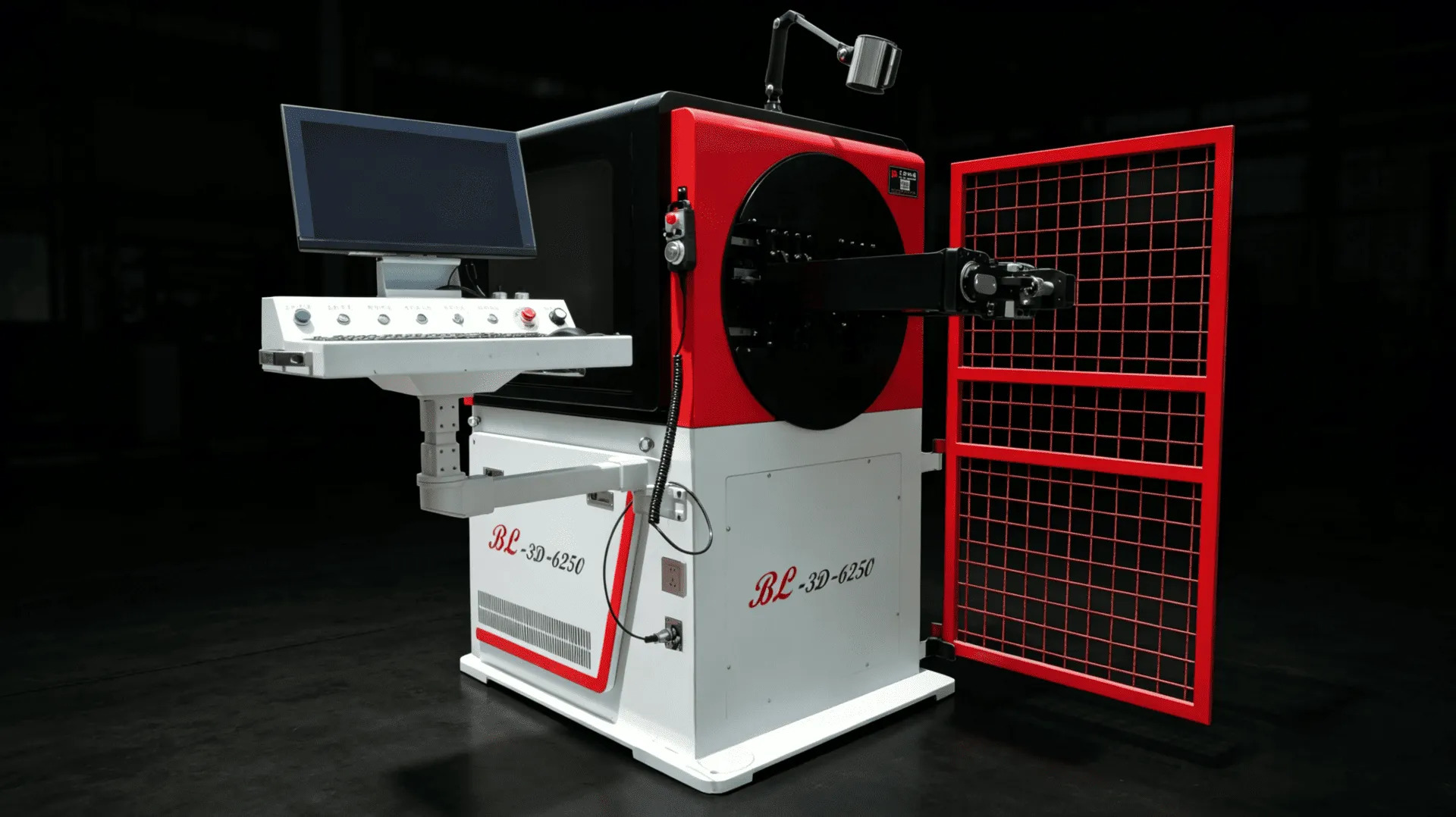
Once a part requires bends in more than one plane, the architecture changes. The wire must be reoriented between features, and this is what rotary-head and multi-axis CNC platforms are built for. A rotary head forming system carries the bending motion around the wire, allowing consecutive bends in different planes without re-clamping the part. For a deeper look at what this capability unlocks, see our overview of the advantages of a 3D wire bending machine.
There is also a middle case: parts that are 2D today but may not stay that way. A product line migrating from flat brackets to formed-and-twisted versions will pay twice if it starts with a strictly planar machine. Where the roadmap is uncertain, the selection should include the next generation of parts, not only the current drawing.
Wire Diameter and Material: The First Filter
Before geometry, capacity decides feasibility. Wire diameter determines the forming force the machine must deliver, the rigidity of the tool set, and the envelope of the feeding and straightening system. A machine specified for fine wire cannot simply be stretched to heavy-gauge stock; the entire force path must be matched to the diameter range the parts actually use.
Material adds a second dimension. Mild steel, high-carbon spring wire, stainless steel, and copper- or aluminum-based wire each behave differently under deformation. Harder, spring-tempered materials demand greater forming force and show more springback; soft, ductile materials mark easily and need smoother tool contact. Two parts with identical geometry can therefore require different machine classes purely because of material grade.
The practical rule is to specify the machine against the most demanding combination in the part mix — the largest diameter, the hardest material, and the tightest bend radius together — rather than the average part. A machine sized for the middle of the range will struggle at the edges, and the edges are usually where new orders arrive.
Part Shape, Bend Count and Forming Complexity
With capacity confirmed, complexity becomes the selection driver. Three characteristics of the part deserve individual attention:
- Number of bends and features — the accumulated effect of small angular errors grows with bend count, so a twelve-bend part demands tighter per-bend repeatability than a four-bend part to reach the same overall tolerance.
- Planar transitions — each plane change requires the machine to reorient the wire or the tool. The number and sequencing of these transitions, not just the total bend count, define how much axis capability the part consumes.
- Closely spaced and interacting features — tight bend spacing, helical sections, offset hooks, and sequence-dependent features challenge the tooling layout; some geometry cannot be reached with a standard tool arrangement.
Annotate the drawing with these characteristics and rank the part against everything else the machine will run. The most complex part — not the highest-volume one — sets the machine requirement, because a machine that cannot form its hardest part has no later fix.
Axes: Matching Capability to the Part, Not the Number
Axis count is the specification buyers quote most and understand least. Axes are not interchangeable; each performs a defined role in feeding, rotating, bending, or positioning the wire. The right question is not "how many axes?" but "which movements does my part sequence need, and does the machine control them independently?"
For flat parts the axis requirement is modest; for 3D parts, rotary motion and coordinated multi-axis control become mandatory, and the differences between machine families start to matter. Our comparison of 5-axis vs 6-axis CNC wire bending machines walks through these roles in detail; the short version is that extra axes translate into forming freedom only when the part sequence actually calls for them.
The same logic applies within our CNC wire bending machine range: each platform is built around a class of geometry and diameter range, and the specification sheets only mean something when they are compared against a real drawing.
Tooling and Changeover for Complex Production
On complex parts, tooling influences the outcome as much as the platform. Bending dies, formers, and guides define the deformation boundary; if tool geometry does not match the wire diameter, material, and bend radius, no axis configuration compensates. Complex 3D parts are especially sensitive, because the wire must stay supported through plane transitions where deformation is least predictable.
Changeover deserves equal weight. Complex part families mean multiple tool sets, frequent program switches, and trial forming after every change. Tooling systems designed for quick, repeatable positioning — and CNC programs that store proven parameter sets per part — turn changeover from a half-day event into a routine task. Ask how the tooling is referenced and how a proven setup is preserved between runs.
Automation Level and Production Volume
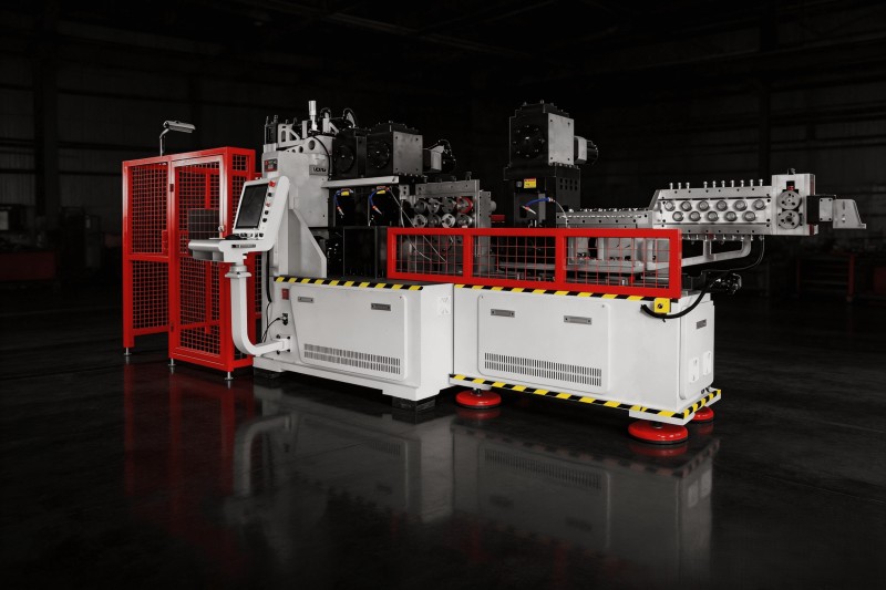
The right automation level follows from the production profile rather than ambition. A single machine with an operator suits mixed, moderate-volume production; integrated forming — feeding, bending, and cutting as one automatic cycle — becomes attractive as volumes rise and labor content per part dominates cost; very high volumes of a stable family can justify a dedicated cell with automatic loading or robotic handling.
Complexity changes the calculation in one way: highly complex parts benefit from automation because manual handling introduces variation at exactly the features that are hardest to hold. Reducing how often an operator re-clamps the wire often contributes more to consistency than any single specification. Where forming connects to downstream assembly, our wire forming robotic automation solution shows how the forming step and material flow are designed together.
When Does a Part Need Custom or Dedicated Equipment?
Most complex parts can be formed on a correctly configured standard platform with appropriate tooling; a smaller group pushes beyond that boundary. Signals that a part may need custom or dedicated equipment include:
- Geometry that combines multi-plane bending with operations such as upsetting, coining, or heading in the same sequence
- Diameters, radii, or material behaviour outside the working envelope of standard platforms
- Tolerances that leave no room for the variation introduced by re-clamping between operations
- Volumes high enough that the fastest possible cycle — with forming steps overlapped rather than sequential — has real commercial value
- Part families that will run for years, where a purpose-built machine amortizes its engineering cost across sustained output
Custom equipment in this sense is not a larger standard machine; it is an engineered system in which forming sequence, tooling, and machine configuration are designed together for one part family. BELAN maintains dedicated engineering for exactly this case — from automotive parts bending equipment to integrated machines that combine forming with heading or cutting — and treats the decision to go custom as a manufacturing question, answered by the part and its volume rather than by preference.
How BELAN Evaluates Drawings and Samples
The most practical selection method is also the simplest: put the real part in front of the machine builder and ask for a formed answer, not a brochure. BELAN's evaluation works from two inputs — drawings and, where available, physical samples:
- From drawings: the engineering team maps the bend sequence, identifies plane transitions, checks each radius against material and diameter, and flags features — tight radii, close spacing, upsetting requirements — that will drive tooling design. The output is a recommended platform, tooling concept, and an honest assessment of which tolerances need trials.
- From samples: a physical part adds information a drawing cannot — actual material temper, surface condition, and how the part deformed. Samples also allow trial forming on candidate platforms, so the buyer sees their own wire formed into their own geometry before committing. This is where customized solutions are scoped with evidence rather than estimates.
This evaluation closes the loop that spec-sheet comparisons leave open: it converts the part's complexity into concrete requirements — platform, axes, tooling, and automation level — before any purchase decision. Within our broader industrial wire forming solutions, the same discipline applies whether the application is automotive, furniture, or general hardware.
Wire Forming Machine Selection Checklist
- ☐ Classify the part as true 2D, true 3D, or migrating between the two
- ☐ Confirm wire diameter range, including the largest expected gauge
- ☐ Confirm material grades and temper, including springback behaviour
- ☐ Count bends, plane transitions, and closely spaced features
- ☐ Check every bend radius against material formability
- ☐ Identify operations beyond bending (upsetting, cutting, coining)
- ☐ Match axis roles to the actual forming sequence
- ☐ Review tooling concept for the most complex part in the mix
- ☐ Evaluate changeover procedure and parameter storage
- ☐ Match automation level to volume and labor cost
- ☐ Request trial forming with your own wire and drawings
- ☐ Confirm tolerance expectations against measured trial parts
Conclusion
Choosing a wire forming machine for complex 2D and 3D components is an exercise in reading the drawing. Plane structure decides the machine family; wire diameter and material set the capacity floor; bend count and feature spacing define how much axis capability and tooling engineering the part consumes; and the production profile decides the automation level. When geometry pushes past standard platforms, custom equipment designed around the part family is the honest answer — reached through a drawing- and sample-based evaluation in which the builder forms your part before you commit. A machine selected this way arrives as a forming solution rather than a set of specifications.
Frequently Asked Questions
1. What is the main difference between a 2D and a 3D wire forming machine?
A 2D machine forms parts in a single plane with one bending axis; a 3D machine reorients the wire or the forming head between bends, producing parts that twist through multiple planes. If any feature requires the wire to rotate relative to the bending motion, a 3D-capable platform is needed.
2. Can a 3D machine also produce simple 2D parts?
Yes — a 3D platform can form flat parts without using its rotary capability. The trade-off is economic: for pure 2D work at high volume, a dedicated 2D machine is usually faster to set up and cheaper to run. The choice depends on whether the part mix will stay flat or evolve toward multi-plane geometry.
3. How does wire diameter affect machine selection?
Diameter drives the forming force, tool rigidity, and envelope of the feeding and straightening system. Machines are built around a diameter range, and a part near the top of that range behaves very differently from one in the middle. Size the machine against the largest diameter and hardest material combination in the planned part mix.
4. How many bends can a CNC wire forming machine handle in one part?
There is no fixed limit — the constraint is the forming sequence, not a counter. What matters is whether each bend can be reached with the available tooling and axis motion, and how accumulated angular error affects overall tolerance as bend count grows. Complex multi-bend parts should be validated by trial forming, not by specification alone.
5. When is custom wire forming equipment justified?
When the part combines multi-plane bending with operations like upsetting or heading, when geometry or material falls outside standard envelopes, when re-clamping variation would break tolerances, or when volumes are high enough to amortize purpose-built engineering. The decision should come from a drawing-based evaluation, not a preference for larger machines.
6. What information does a supplier need to recommend a machine?
Ideally four things: part drawings with dimensions and tolerances, the wire specification (material grade, diameter, temper), expected production volume, and — most valuable — a physical sample if one exists. With these, the supplier can map the forming sequence and propose a platform and tooling concept with evidence behind it.
7. Should I buy for the parts I make now or the parts I plan to make?
Buy primarily for current production, but evaluate the roadmap honestly. A platform covering the next generation of parts avoids a second purchase, while over-buying capability for a flat, stable mix ties up budget without return. Trial forming on both current and planned geometry makes this trade-off concrete.
Need a Forming Solution for Your 2D or 3D Wire Components?
BELAN Machinery, a professional provider of automotive wire forming solutions. Send us your part drawings, samples, and wire specifications, and our engineering team will evaluate the forming sequence and recommend the right machine configuration and tooling for your production.
Contact Belan for a Feasibility AssessmentRelated Resources
- 2D Wire Bending Machine — High-efficiency planar forming platform for flat wire components.
- Rotary Head CNC Wire Bending Machine — Multi-plane forming capability for complex 3D wire geometry.
- Customized Solutions — Tailored machine and tooling configurations for special part families.
- Industrial Wire Forming Solutions — End-to-end forming solutions across industrial applications.
- How to Choose a CNC Wire Bending Machine — Step-by-step selection framework from capacity to automation.