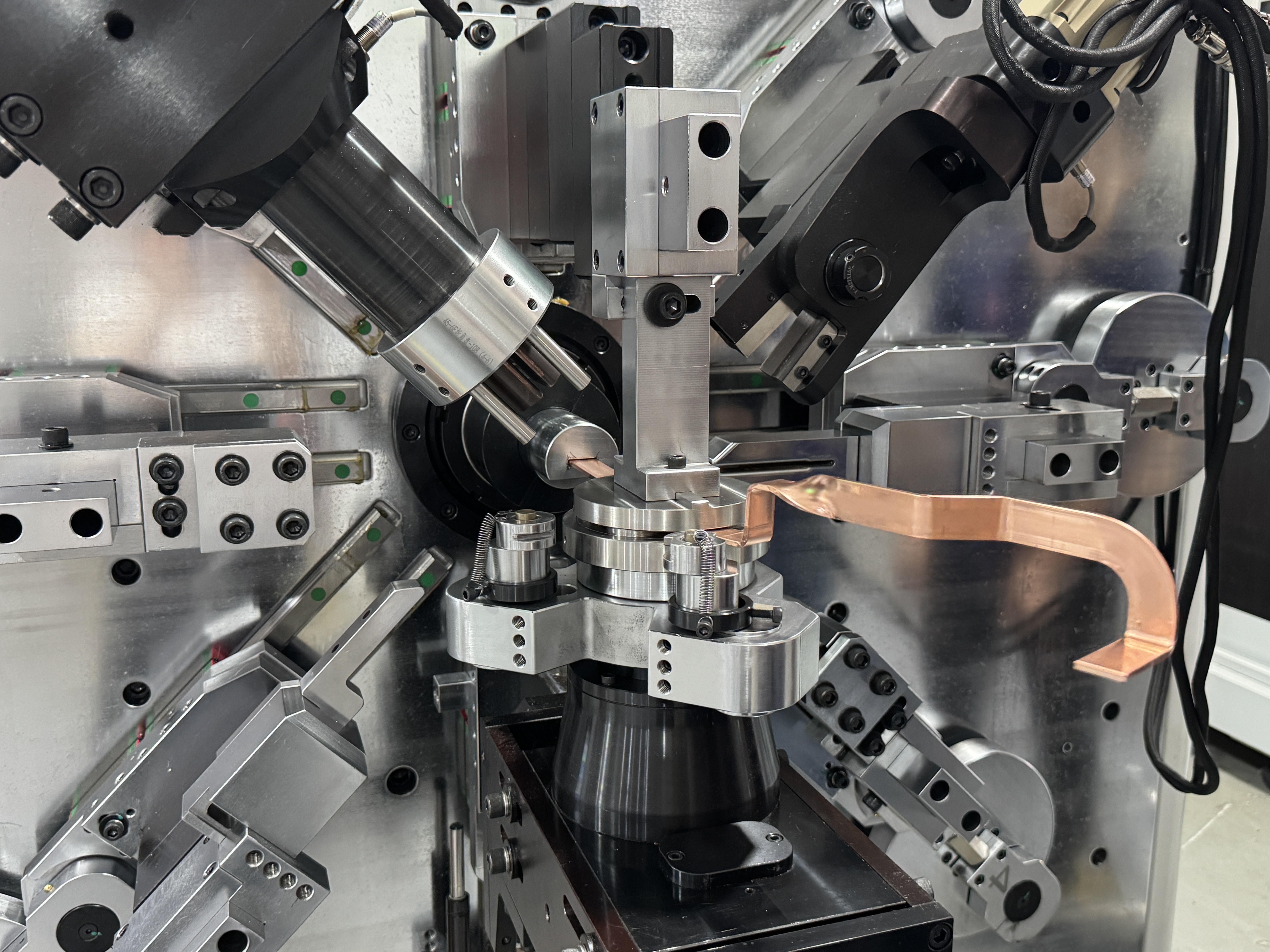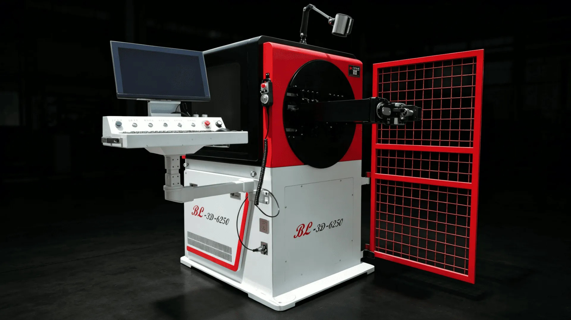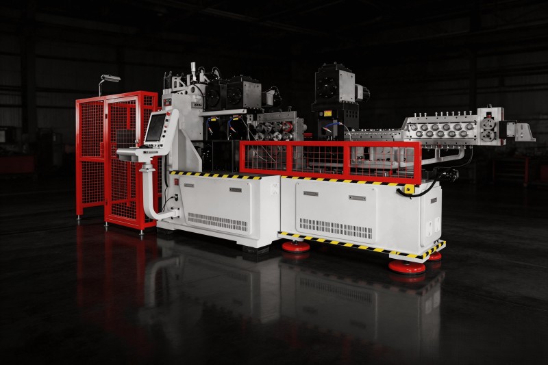


Holes, slots, pressed teeth and logos on a wiper arm are flat features. Draw them wherever you like on the print — if they are scheduled after the bend, they turn into a scrap plan. A wiper arm bending machine puts punching, pressing and marking before bending not because of layout convenience, but because the dies and the datums demand it. Here is the reasoning behind that sequence, so you know what to check when you send a drawing out for evaluation.

Bending Destroys Three Datums at Once
First, the locating datum. Hole, slot, tooth and logo positions are all dimensioned from a flat, straight face. Straightened flat bar laid on a table gives every feature a clean 2D coordinate; once the arm is bent, it is a 3D part, and the same operator clamping it two different ways will measure two different positions. Second, die access. Punching and pressing need a flat support under the feature and a vertical press stroke. A bent arm hangs and interferes — the die either cannot reach the feature or cannot seat it properly. Third, the stress face. The outside of a bend is in tension, and a hole or slot near the bend line lands a burr and work-hardened edge exactly where a crack wants to start. That is why drawings put holes and slots in the flat zones away from the bend line — and why the process order has to cooperate, punching first and bending after.
What Happens When the Order Is Wrong
Move bending ahead of punching and three failures take turns showing up. Hole positions drift, because repeat locating on a 3D part eats the hole tolerance directly. Holes crack at the edge, because a late-punched burr sits on the tension face and the fracture follows it. Teeth and logos press unevenly, because without flat support the depth varies from part to part and from one side of the marking to the other. None of these can be repaired downstream.

How the Machine Locks the Sequence In
The processing chain on our wiper arm bending machine (BL-YG-12A) is arranged exactly along that order: coil onto the twin-end payoff, feed, straighten, punch and slot and press teeth and stamp the logo in the flat zone, then bend with synchronized inner and outer rotary heads — side bends, vertical bends and twist bends — and finish with a pre-loaded cut-off. Twelve full-servo axes drive this flow: three 7.5KW punching motors handle the flat features, a 7.5KW feeding motor carries the bar, and two 4.4KW turning motors form the bends, on a 55.9KW total with a 500mm bending stroke and a 16000KG frame. It runs flat wire sections of 4×9mm and 4×12mm. This structure is what the wiper arm bending machine integration story is built on — five or six operations that used to need three to five machines and manual transfer now run on one floor space. The sequence is welded into the structure, not memorized by the operator, so the order survives every shift change.
Sequence at a Glance
| Operation | Position | Why here | Cost of doing it after the bend |
| Straightening | First | Straight bar is the datum for every hole position; indexed rolls record settings | — (foundation step) |
| Punching / slotting | Flat zone, before bending | Flat locating, vertical die stroke | Poor locating on a 3D part; burrs crack on the tension face |
| Tooth pressing | Flat zone, before bending | Flat support keeps depth uniform | Uneven depth, slippage |
| Logo stamping | Flat zone, before bending | Flat face gives a clean, consistent mark | Uneven marking face and depth |
| Bending (side / vertical / twist) | Middle-late | Synchronized rotary heads, 500mm stroke | — (core forming step) |
| Cut-off (pre-loaded) | Last | Pre-load stabilizes the cut, limits burrs | — (closing step) |
Four Questions I Ask When a Drawing Comes In
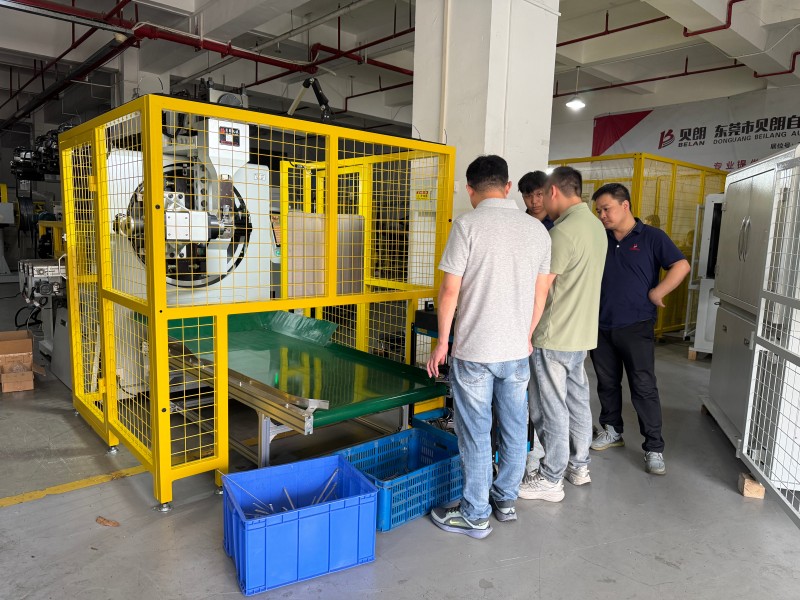
First, the distance from hole and slot centers to the nearest bend line — it decides whether the feature clears the tension zone and keeps a flat landing for the punch. Second, which face carries the pressed teeth and the logo, so we can confirm the dies reach them before bending. Third, how the bend directions combine — side, vertical and twist bends each get their own inner/outer rotary coordination on a wiper arm bending machine. Fourth, batch size and changeover: different arm variants mainly swap the pressing and cut-off dies, both with locating lock devices, and the honest way to cost changeover is from last good part of one variant to first good part of the next. When DOGA came to our floor for on-site acceptance, the check sheet followed the same logic — total length, bend position and angle, hole position, cut edge and surface, run through in drawing order. Answer those four and you basically know whether your arm can run through a wiper linkage arm forming machine in one pass — it is also step one of any serious wiper arm manufacturing process review.
Sequence Is the First Lever on Scrap
Half of what a wiper arm bending machine saves comes from fewer machines and operators; the other half comes from the sequence itself — flat features land in one pass, and hole positions, tooth depth and marking stay consistent across the batch. Send us the arm drawing with the hole positions, pressing face and bend directions marked, and we will walk it through this sequence and tell you which features belong in the flat zone and which genuinely need post-bend handling. Choosing the right wiper arm bending machine starts with putting the operations in the right order. BELAN Machinery, your expert provider of automotive wire forming solutions.