

When sourcing a CNC busbar bending machine, qualify the inside bend radius separately for flatwise and edgewise bends. You can specify the same finished inside radius for both directions if trials on production-intent material show that both bends meet the drawing and fit the assembly. A flatwise sample alone gives you evidence for the flatwise bend. For an edgewise bend, ask for its own sample and measurement record before approving the tooling.
This guide applies to solid rectangular copper busbars, such as links in switchgear and power distribution assemblies. Use the finished part drawing to define the required radius, then use sample bends to judge whether the supplier can produce it consistently.
How bending direction changes the radius decision
Let W be the width of the copper bar and T its thickness. The inside radius, or R, is measured on the concave side of the finished bend after the part is released from the tooling.
| What to compare | Flatwise bend | Edgewise bend |
|---|---|---|
| How the bar curves | Out of the plane of the broad face | In the plane of the broad face |
| Cross-section dimension from inside to outside of the bend | Thickness, T | Width, W |
| What to check on the trial part | Outer bend surface, finished angle and radius, and leg dimensions | Outer edge for cracking, inner edge for buckling or distortion, finished angle and radius, and twist |
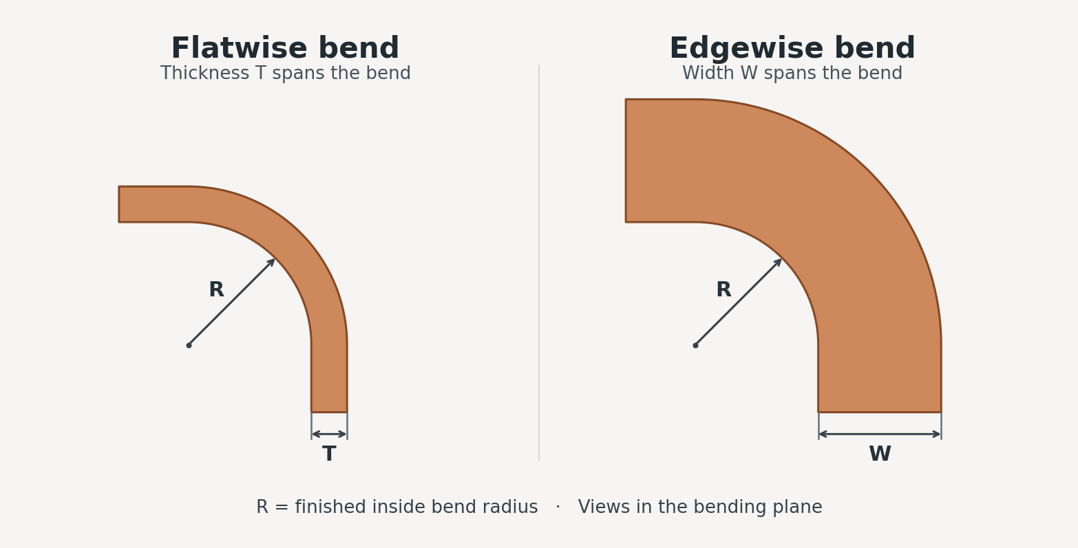
For a 30 mm wide × 5 mm thick bar, the inside-to-outside dimension is 5 mm in a flatwise bend and 30 mm in an edgewise bend. At the same inside radius, the edgewise orientation can stretch the outer material more because the bend spans the wider dimension. The example illustrates the geometry. The achievable radius still depends on the copper grade and temper, cross-section, edge condition and tooling. See Bending Copper Busbars for Switchgear and Control Panels.
How to establish the minimum bend radius for your part
Start with the radius your assembly can accommodate. Specify the copper grade and temper, width and thickness, bend direction, finished inside radius and angle on the drawing. Mark the mounting faces and hole centres that control assembly fit. Include any surface or edge requirements the supplier must meet. Where the available space allows, give the supplier an acceptable radius range so engineering can evaluate tooling options.
Published bend-radius tables can help with the initial drawing review. Table 6 in the Copper Development Association and European Copper Institute guide, for example, gives thickness-based guidance for high-conductivity copper in half-hard or hard temper. Treat it as a starting point within that material scope. Qualify an edgewise bend using the actual width, temper and tooling, and requalify if the design changes to aluminium or to stock with a different coating or insulation. See Copper for Busbars, section 1.2.2.2.7 and Table 6.
What to measure in a supplier bend trial
- Use the material you intend to buy. For a like-for-like comparison, make flatwise and edgewise trial pieces from the same batch, with the same grade, temper, cross-section and edge condition. Ask the supplier to identify the machine configuration and tooling used for each direction.
- Record the tool radius and the finished radius separately. Agree on a method suited to the drawing tolerance, such as profile measurement. After releasing the part, measure the inside radius and finished angle. Springback is the elastic recovery after release. Where the trial can capture the loaded angle, record it alongside the released angle. Record any programmed overbend separately so the two values can be interpreted correctly.
- Check the complete part in its assembly position. Include a production-intent part with its actual bends and holes. Use the drawing datums to check leg lengths, hole positions, contact-face alignment and twist where applicable. Seat the part in the inspection fixture without forcing it. Agree on how the supplier will document surface condition and any cracking or distortion.
- Agree on the acceptance run. Before signing off the tooling or equipment, set sample quantities, measurement methods, drawing tolerances and the applicable cycle-time target. If you plan to verify these at the factory acceptance test (FAT), include the critical edgewise bend and the most demanding finished part in the test plan.
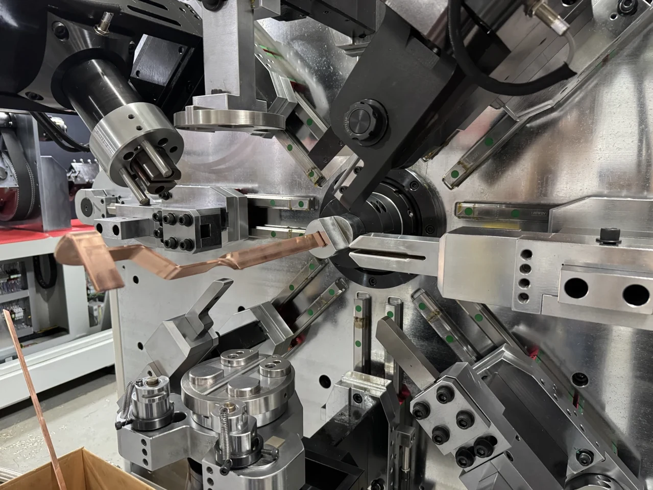
If the edgewise sample fails at the specified radius, review the tooling and ask whether the assembly can accept a larger inside radius. Have the design owner approve any change to the drawing, then repeat the trial against the revised requirements.
Check bend allowance at the same time. Bend allowance is the length assigned to the curved portion when developing the blank. Confirm it for each bend direction using measured trials so the cut length and punched holes match the finished drawing. Then verify the developed length and hole positions on a complete part. See Autodesk’s explanation of measured bend tables.
Use the drawing to shortlist a BELAN machine
BELAN starts with the part drawing, material, cross-section, tolerances and planned output. For example, the BL-TP-50-7E lists a copper busbar range of 15–45 mm in width and 1.0–7.0 mm in thickness. The 30 × 5 mm example falls within that range, so the machine can be shortlisted for review. Engineering still needs to check the requested radius, bend direction, tooling and finished-part geometry. BL-TP-50-7E specifications.
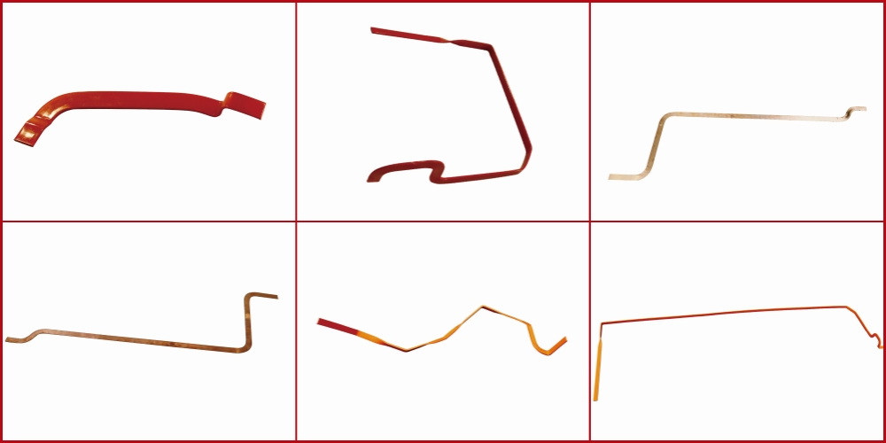
For a quotation or sample review, send BELAN the drawing revision, copper grade and temper, cross-section, bend directions, finished radius and angle tolerances, and expected production volume. If fixture fit decides acceptance, include a fixture drawing or the key assembly datums. Ask for a trial on the hardest-to-form part before finalising the equipment and tooling. BELAN busbar bending machines and quotation enquiries.