
Introduction
Selecting a busbar bending machine is rarely a question of finding the machine with the largest tonnage or the longest feature list. It is a question of matching equipment capability to two things: the busbars you actually process, and the production pattern you actually run. Copper and aluminum make that match harder, because the two materials behave differently under the same bending force, on the same tooling, at the same bend radius.
A machine that produces clean bends in copper may mark or crack aluminum. A configuration sized for one busbar width may be oversized for another. This guide sets out a practical selection framework: material behaviour first, then part requirements, machine capacity, automation level, and finally validation before the purchase is signed.
Why Copper and Aluminum Busbars Behave Differently on the Same Machine
Copper and aluminum are both chosen for conductivity, but they are not interchangeable from a forming perspective. Their mechanical properties and surface behaviour differ enough that a single selection decision — bending force, tooling radius, clamping pressure, or surface protection — can be correct for one material and wrong for the other.
- Strength and springback — copper busbars generally require higher forming force and exhibit more springback, especially in harder tempers. Aluminum is softer and lighter, but its recovery behaviour varies by alloy and temper, so compensation values rarely transfer between the two.
- Ductility and bend limits — aluminum can be more prone to cracking at tight radii depending on alloy and temper, while copper usually tolerates tighter bends but needs firmer support to hold angle accuracy.
- Surface sensitivity — both materials mark easily if tooling contact is rough or clamping pressure is excessive, and surface damage matters because it affects conductivity and downstream plating or insulation.
- Oxide layer — aluminum forms an oxide layer quickly, which influences how the material is handled, cleaned, and joined after bending, and therefore how closely bending and subsequent operations need to be sequenced.
Start With the Part: Defining Busbar Processing Requirements
Before comparing machines, define the parts. A specification written around real drawings prevents both oversizing and unpleasant surprises after installation. The key inputs are straightforward:
- Material and thickness range — which grades and tempers, and the minimum to maximum thickness you will run in production, not just on the sample drawing
- Width range — the narrowest and widest busbar the machine must handle, plus any flat-on-edge orientations
- Bend geometry — flat bends, edgewise bends, offsets, U-shapes, multi-layer stack bends, and the tightest radius in the part family
- Process scope — whether the machine only bends, or also cuts to length, punches, notches, embosses, or marks
- Tolerances — dimensional and angle tolerances that downstream assembly, welding, or bolted connections actually require
- Bar length and feeding format — whether you feed cut-to-length bars or work from coils, which changes the machine concept considerably
Matching Machine Capacity to Busbar Size and Thickness
Bending force, and therefore machine capacity, scales with busbar width, thickness, and material strength. A narrow copper bar and a wide aluminum bar of the same thickness can demand very different forces, and the widest, thickest, hardest part in your range sets the floor for capacity — not the average.
Two ratios matter when reviewing a machine's specification. The first is thickness versus width: at a given force, a change in width affects the required load more than a proportional change in thickness might suggest, and machines are typically rated for specific width-thickness combinations rather than a single maximum figure. The second is bend radius versus thickness: as the radius becomes tighter relative to thickness, strain on the outer surface rises and the risk of cracking or surface damage increases.
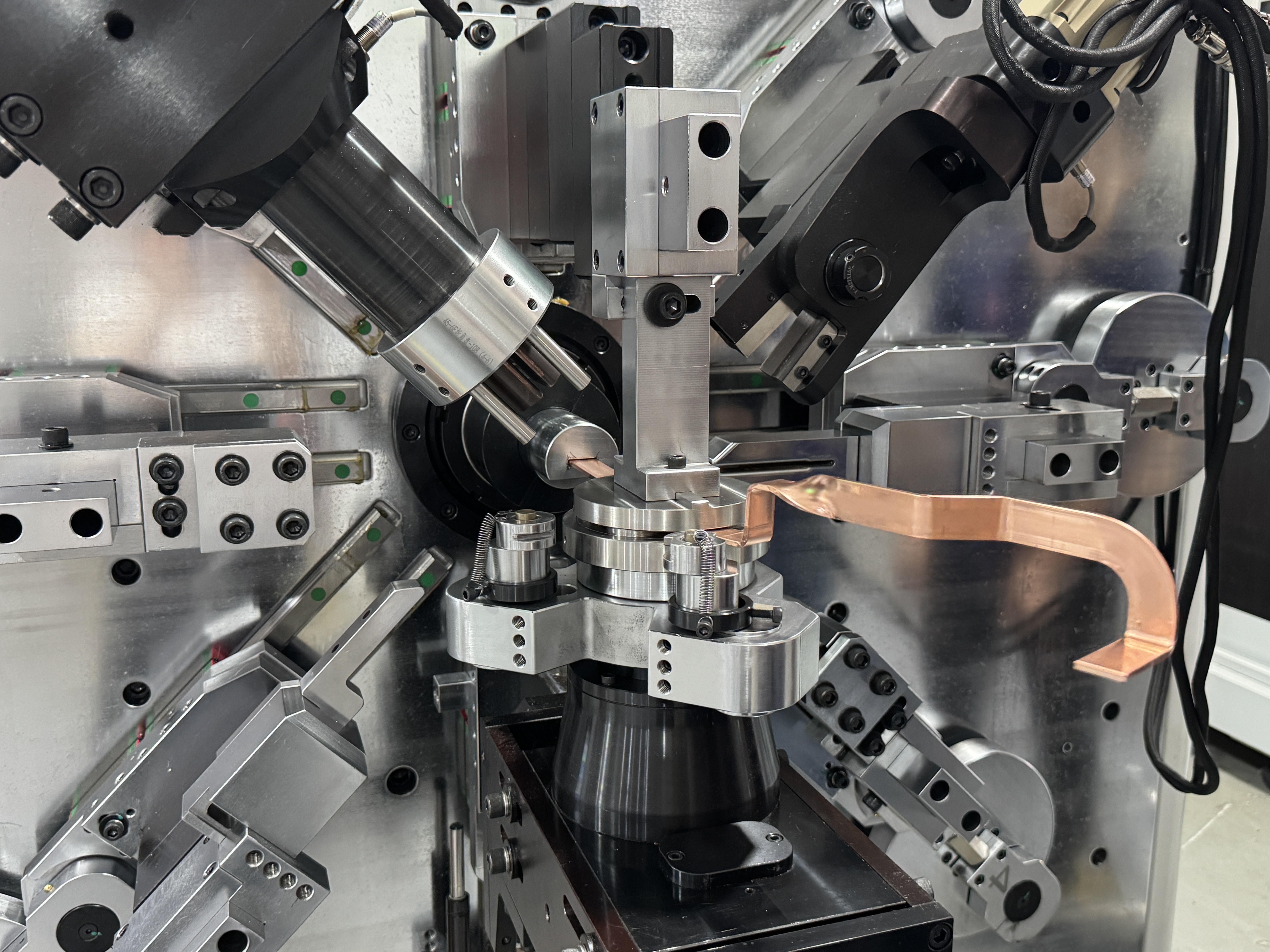
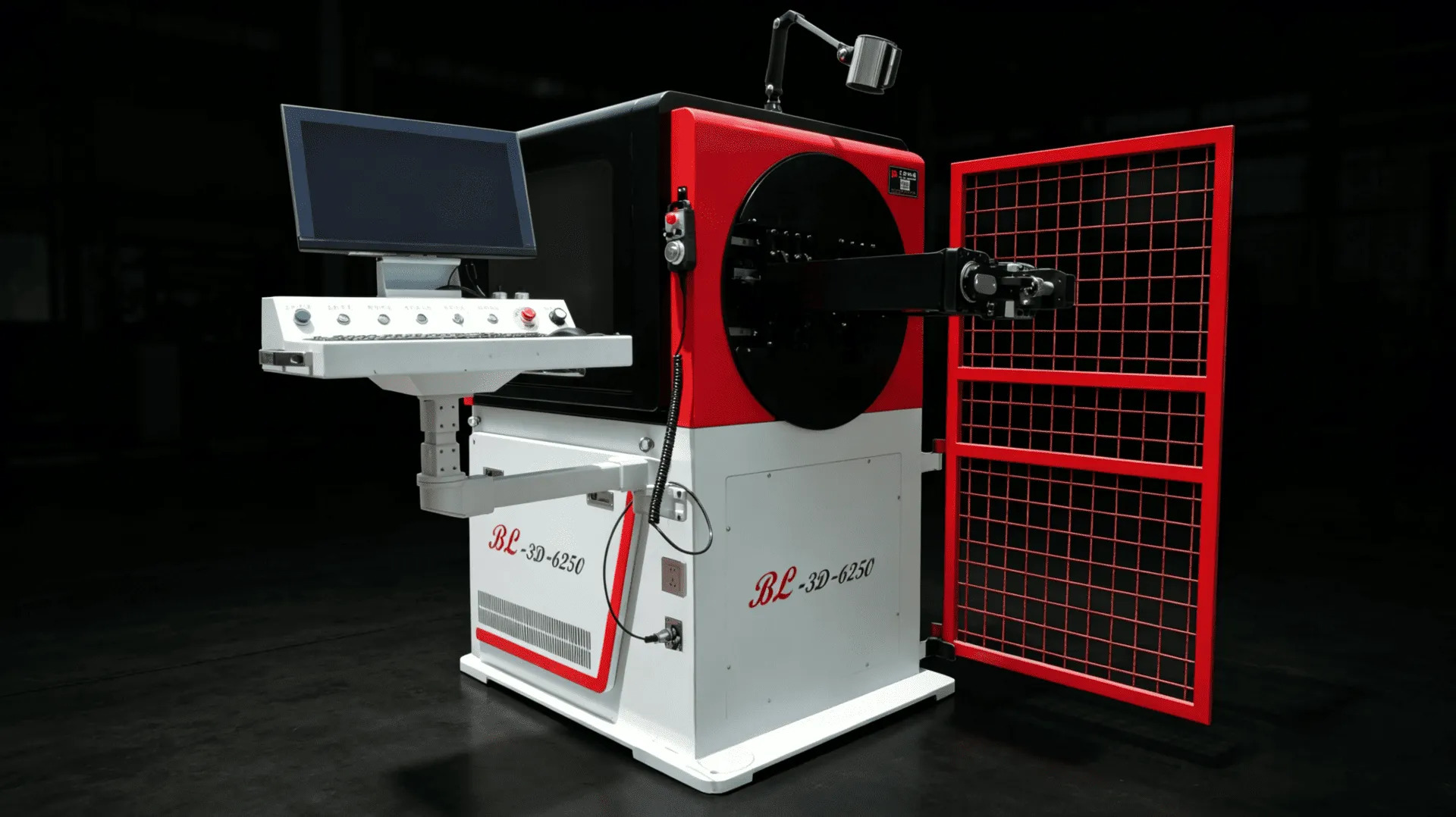
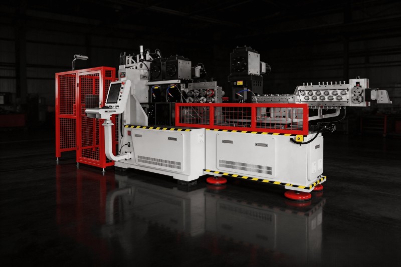
Ask for the specification in the form you will actually run. A machine rated for a maximum width at minimum thickness may not process that same width at maximum thickness. Where the requirement sits at the edge of a standard model's range, step up or confirm the combination in writing. The BL-TP series is one example of a machine family structured around copper-aluminum busbar processing; the BL-TP-45-6E model page shows how capacity is documented for a specific configuration.
Bending Methods and Tooling: What to Evaluate
How a machine forms the bend is one of the most consequential selection decisions, and it is decided by the part rather than by the machine's marketing. Rotary, die, servo-rotary, and multi-axis approaches each leave a different fingerprint: maximum angle range, minimum achievable radius, surface contact, changeover effort, and how well the machine handles multi-bend parts without repositioning.
For a single simple L-bend at moderate volume, a straightforward rotary configuration is often sufficient. For parts with several bends in different planes, or for copper bars where angle accuracy and surface condition are both critical, multi-axis servo forming usually earns its cost through fewer setups and more repeatable angles. The detailed comparison of these methods is covered in choosing the right bending method for a copper-aluminum busbar machine.
Tooling deserves equal attention. Die radius, contact geometry, and clamping surfaces determine whether the finished bend meets the drawing and whether the surface remains acceptable. Because copper and aluminum respond differently to the same tool set, ask whether tooling is material-specific, how radii are selected, and how quickly dies can be changed when the part family changes.
Feeding, Positioning and Control Systems
Feeding and positioning determine whether the machine's stated accuracy is actually reachable in production. Positioning error shows up directly in bend location along the bar, while feeding mechanism choice affects surface condition, changeover time, and how the machine handles long or heavy bars.
The practical question is not which feeding structure is technically superior, but which one fits your bar range and production mix. Track, roller, and clamping systems differ in grip, marking risk, and the effort required when the bar changes. That trade-off is examined in the comparison of feeding structures for copper-aluminum busbar bending machines.
Control and operation should also be evaluated from the operator's side of the machine. Programming effort per new part, on-screen feedback during debugging, parameter storage, and how easily proven settings are repeated all influence effective output far more than nominal axis resolution. Where changeover frequency is high, platform ergonomics and the way programs are called up can decide whether a machine pays for itself. These aspects are covered in operation platform design for higher debugging efficiency.
Matching Automation Level to Production Volume
Automation is the largest cost variable in the selection, and it should be driven by volume and labour structure rather than by ambition. Three broad levels cover most busbar production:
- Single-machine processing — one machine performs bending, with manual or semi-automatic loading. Suitable for high-mix, lower-volume work where flexibility matters more than cycle time.
- Integrated forming — cutting, punching, and bending combined in one machine sequence, which reduces handling, work-in-progress, and the dimensional drift that appears when parts move between machines. This is the typical answer to mid-to-high volume busbar production in electric drive and BMS applications.
- Linked production lines — bending combined with laser marking, robot handling, or downstream operations in a coordinated line, justified when volume is high and process consistency must be maintained across several operations.
For context on how these levels map to real busbar work, see EV busbar processing solutions and busbar bending and laser robot integrated production lines.
Surface Quality and Electrical Performance
A busbar is a conductor, not just a formed part. Bends, marks, and section deformation all affect how the current-carrying path behaves, and they matter more in insulated or laminated assemblies where surface damage can compromise subsequent processing.
Two evaluation points follow from this. First, tooling and clamping should be reviewed for contact pressure and surface finish, particularly where aluminum or plated material is involved. Second, over-bending to compensate for springback can be counterproductive if it produces thinning or cracking on the outer surface; the objective is a bend that holds its angle without damaging the conductor. If a supplier can only describe accuracy in terms of axis positioning, ask how they protect the bending surface.
Questions to Ask Before You Buy
A structured set of questions quickly separates a machine that fits from one that merely looks capable on a specification sheet:
- Is capacity rated for my exact width–thickness combinations, in both materials?
- How were springback compensation values established, and how are they stored and reused?
- What radius can be achieved in my material without surface damage or cracking?
- How long does a changeover take between two of my part numbers?
- Which functions are integrated, and which still require a second machine or manual handling?
- What tooling is included, what is material-specific, and what does replacement cost?
- What support exists for commissioning, training, and long-term spares?
Trial Bending and Acceptance Testing
The final selection step is verification with your own material. Send real busbar samples, not photos, and define what a successful trial means in advance: which dimensions and angles are measured, what tolerance is acceptable, how the surface is judged, and how many consecutive parts must repeat within tolerance.
A trial that produces one good part proves very little. Ask for a run long enough to show repeatability, ideally across both materials if both are in scope, and across the extremes of your size range. Record the settings used, because those values become the baseline for your production program — and if they cannot be reproduced at acceptance, they cannot be reproduced six months later either.
Busbar Bending Machine Selection Checklist
- ☐ Define material grades and tempers for copper and aluminum
- ☐ List busbar width and thickness ranges (minimum to maximum)
- ☐ Identify the tightest bend radius in the part family
- ☐ Confirm bending force at the worst width–thickness combination
- ☐ Review bending method against bend geometry and volume
- ☐ Evaluate tooling radius and surface protection
- ☐ Check feeding structure against bar length and weight
- ☐ Verify positioning accuracy in production conditions
- ☐ Match automation level to volume and labour structure
- ☐ Confirm process scope: bending, cutting, punching, marking
- ☐ Trial bend with your own material and measure repeatability
- ☐ Record proven settings and agree acceptance criteria in writing
Conclusion
Choosing a busbar bending machine for copper and aluminum comes down to sequence: define the material behaviour, define the parts, size the machine to the hardest combination in that range, then decide how much automation the volume justifies. Each step constrains the next, and skipping one usually surfaces later as rework, rejected bends, or a machine that only performs well on the sample it was sold with.
The final filter is verification. A supplier willing to trial your material, document the settings, and discuss repeatability openly is offering more than a specification — they are offering a process you can run.
Frequently Asked Questions
1. Can one busbar bending machine handle both copper and aluminum?
Usually yes, provided the machine's capacity is rated for the hardest combination in your range and tooling is matched to each material. The practical constraint is not the machine concept but springback compensation and surface protection: copper typically needs more force and different compensation values than aluminum, so proven settings should be stored per material and per part.
2. How do I determine the required bending force?
Start from the widest, thickest, hardest busbar you will run, and confirm the machine rating for that exact combination rather than for a single maximum figure. Force requirements rise with width, thickness, and material strength, and they rise again as bend radius tightens relative to thickness. Your supplier should confirm the rating against your drawings.
3. What busbar thickness and width range should a machine cover?
Cover the full range you expect over the machine's service life, including products still in development, not only current production. It is usually cheaper to select slightly more capacity than to discover after installation that a new program needs a width-thickness combination outside the machine's rated envelope.
4. Is a CNC machine necessary for low-volume busbar production?
It depends on part complexity rather than volume alone. If parts involve several bends, tight angle tolerances, or frequent changeovers, CNC control usually pays back through faster setup and repeatable settings even at modest volumes. For simple single-bend work, a less automated configuration may be adequate.
5. Why does bend radius matter more with aluminum?
Aluminum's formability varies significantly with alloy and temper, and tighter radii increase strain on the outer surface, raising the risk of cracking or surface damage. Because the safe radius differs by material, radius limits should be confirmed by trial bending with the exact grade and temper you will use in production.
6. Should cutting and punching be integrated with bending?
Integration reduces handling and work-in-progress, and it removes the dimensional drift that appears when parts move between separate machines. It is generally justified at higher volumes or where process consistency matters, such as in battery and electric drive busbars. At low volume with simple parts, separate operations can remain practical.
7. How do I verify accuracy before buying?
Insist on a trial with your own busbar samples, across your size range and both materials if applicable. Define the measurements, tolerances, surface criteria, and sample size in advance, and ask for a run long enough to demonstrate repeatability rather than a single good part. Record the settings used and confirm they can be reproduced.
Need Help Choosing the Right Busbar Bending Machine?
BELAN Machinery, a professional provider of automotive wire forming solutions. Send us your busbar drawings, material grades, thickness and width range, and production requirements. Our engineering team can evaluate your bending and processing needs to help develop a suitable copper-aluminum busbar forming solution.
Contact Belan for a Feasibility AssessmentRelated Resources
- Rotary, Die and Multi-Axis Servo: Choosing the Right Bending Method — Compares bending methods for copper-aluminum busbar machines on precision, surface protection, and changeover.
- Comparison of Three Feeding Structures for Busbar Bending Machines — Analyses track, roller, and clamping feeding on compatibility, precision, and changeover cost.
- Operation Platform Design for Higher Debugging Efficiency — Explains how movable and fixed platform designs affect debugging and part changeover.
- EV Busbar Processing Solutions — Processing approaches for copper and aluminum busbars used in electric drive and battery systems.
- Busbar Bender Auxiliary Feeding Device and Change-over Efficiency — Discusses how auxiliary feeding devices influence changeover efficiency in busbar production.